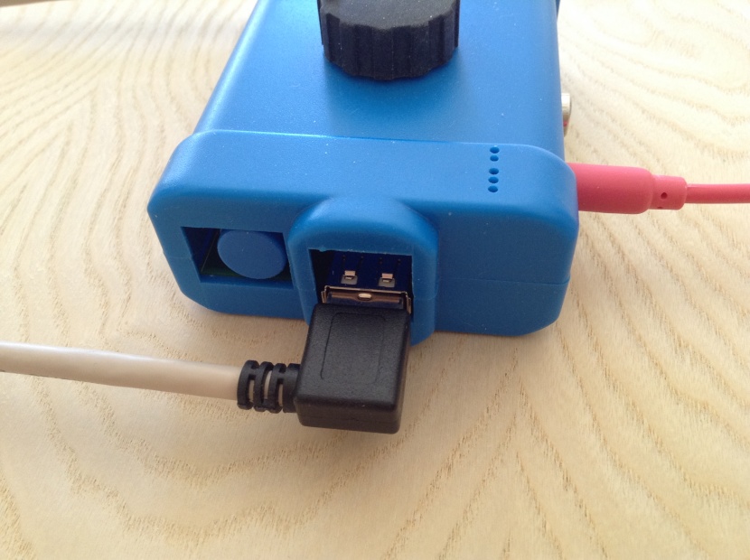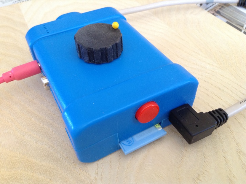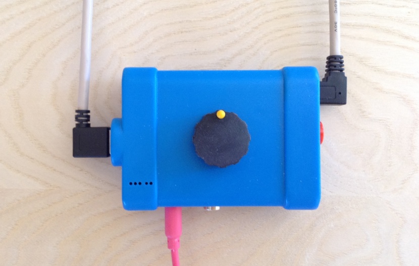
Airband radio receiverAll civil air traffic control (ATC) voice radio is broadcasted totally open and unencrypted in the "aviation band", which comprise a number of reserved channels between 118 and 134 MHz. Provided that you have a suitable receiver or scanner equipment, it is not difficult to locate a channel and start listening -- even though it may not be obvious to the layman exactly what all the slurred cryptic messages mean! The components that make up this project, both hardware and software-wise, consists mostly of off-the-shelf (or rather off-the-web) readymade stuff. Practically the only handcrafted parts are the antennas (antennae, aerials), their cabling and some proto-board soldering. For a write-up of my "companion" ADS-B receiver see here. A description of the aviation band receiver part follows on this page. AntennaThe type of outdoors antenna that is easiest to construct is perhaps the dipole, and that is what we settled for. For a nominal target frequency of 127 MHz (which is the rational medium of the interesting frequency span of 118 to 137) the quarter-wavelength dimension is 590 mm. I used 15 mm (chromed) copper tubing. The two arms (each 560 mm long) are joined by a plastic dowel as close as possible (with plastic washer for separation) and the connections of the coaxial leads protected by a simple watertight junction box. Type RG59 coaxial was used for both antennas. This type has nominally 75 Ohm impedance, while the aviation band receiver expects 50 0hm. To somewhat compensate for line loss due to this discrepancy the first cable was carefully cut to a length corresponding to a multiple of a 1/2 wavelength of the target frequency. The rationale behind this trick is described here, for instance. 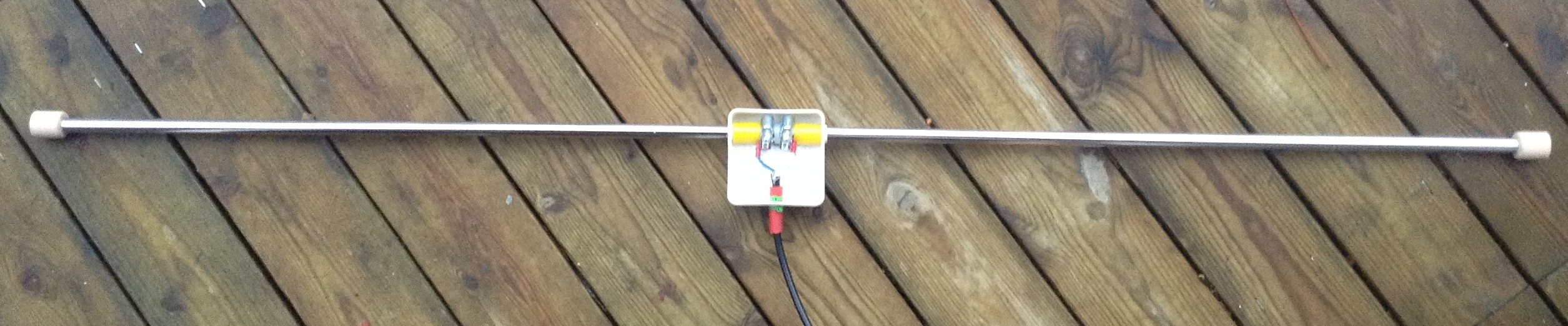  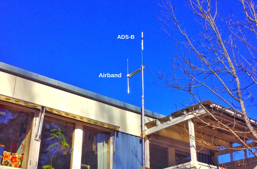 Analogue receiver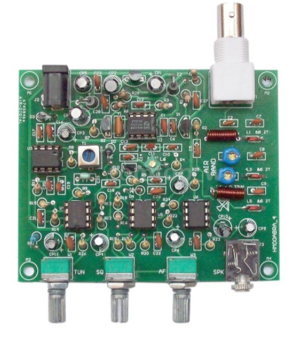 For a basic aviation band analog receiver one doesn't have to look further than ebay. A DIY PCB-kit with all the through-hole parts required was bougth from China for less than USD 15.00. The instructions were a little vague on the critical orientation of some parts, but it turned out to work fairly well, considering the price. Reception tends to fade in and out, and the frequency regulating potentiometer range is perhaps unneccearily wide which makes it fiddly to tune in exactly. The finished kit is just the exposed PCB, so it needs a fitting enclosure. A wooden box from a small IKEA cupboard fitted perfectly. The front panel is a piece of countertop laminate sample. Knobs and standoffs are courtesy of the scrap-box. The control pots are for tuning, squelch and volume. The performance of this station was not too bad considering the unsophisticated components. However, the tuning is always unstable and lacking a proper frequency dial it easily gets very frustrating to grope around for a particular channel. 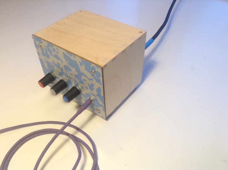 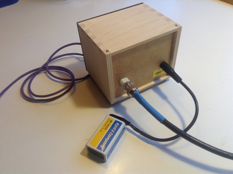 If you are not yet familiar with RTL-SDR, suffice it to say that it is a (free and open-source) software defined radio, SDR, that rather magically turns a Realtek RTL2832 based DVB dongle into a formidable SDR receiver. Basically, this means that a cheap TV tuner USB dongle can be used as a computer controlled radio scanner. This powerful piece of digital radio hardware became the basis for our second airband receiver attempt. Compared to the standard DVB dongle used in our ADS-B project this time we pair an enhanced USB dongle from RTL-SDR.COM with an old Model A Rasperry Pi. And, as usual when doing a fresh Raspbian install, and before anything else, it is prudent to change username and password from the defaults, expand the system on the flash-disc, and enable remote login. 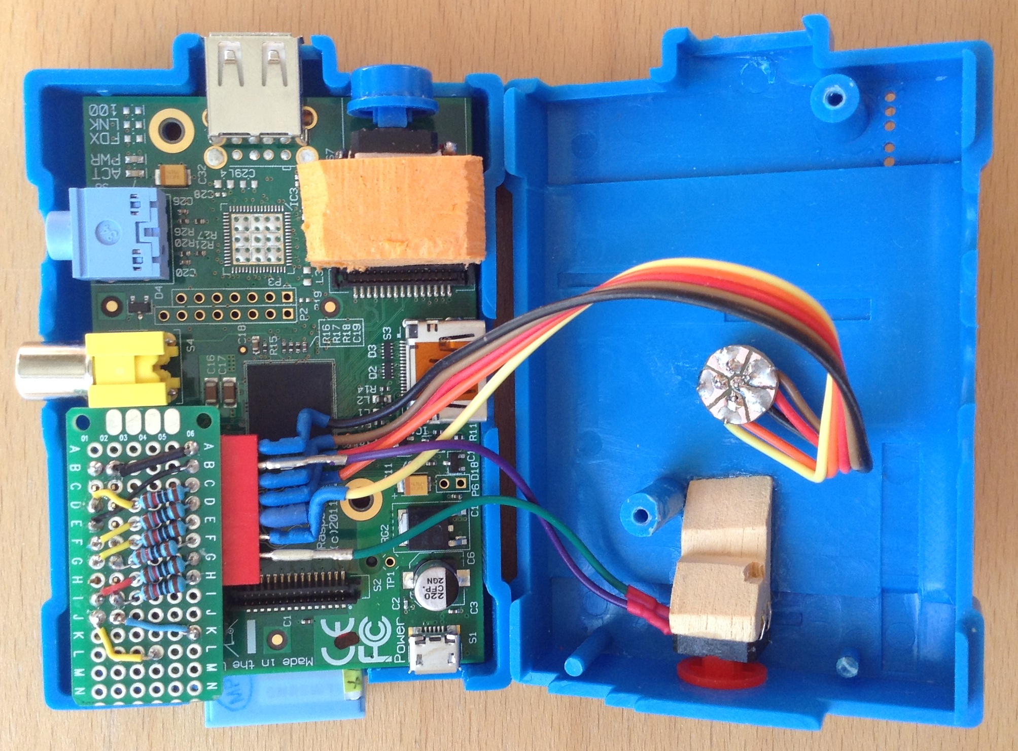 This is the physical pinout (as per BCM GPIO numbering scheme) used in this implementation: RPi: Connected to: 4 Switch <SHTDWN> 15 Piezo buzzer 18 Switch <ENTER> 22 Encoder: LSB (1) 23 Encoder: 2nd (2) 24 Encoder: 3rd (4) 25 Encoder: 4th (8) GND Common USB SDR dongle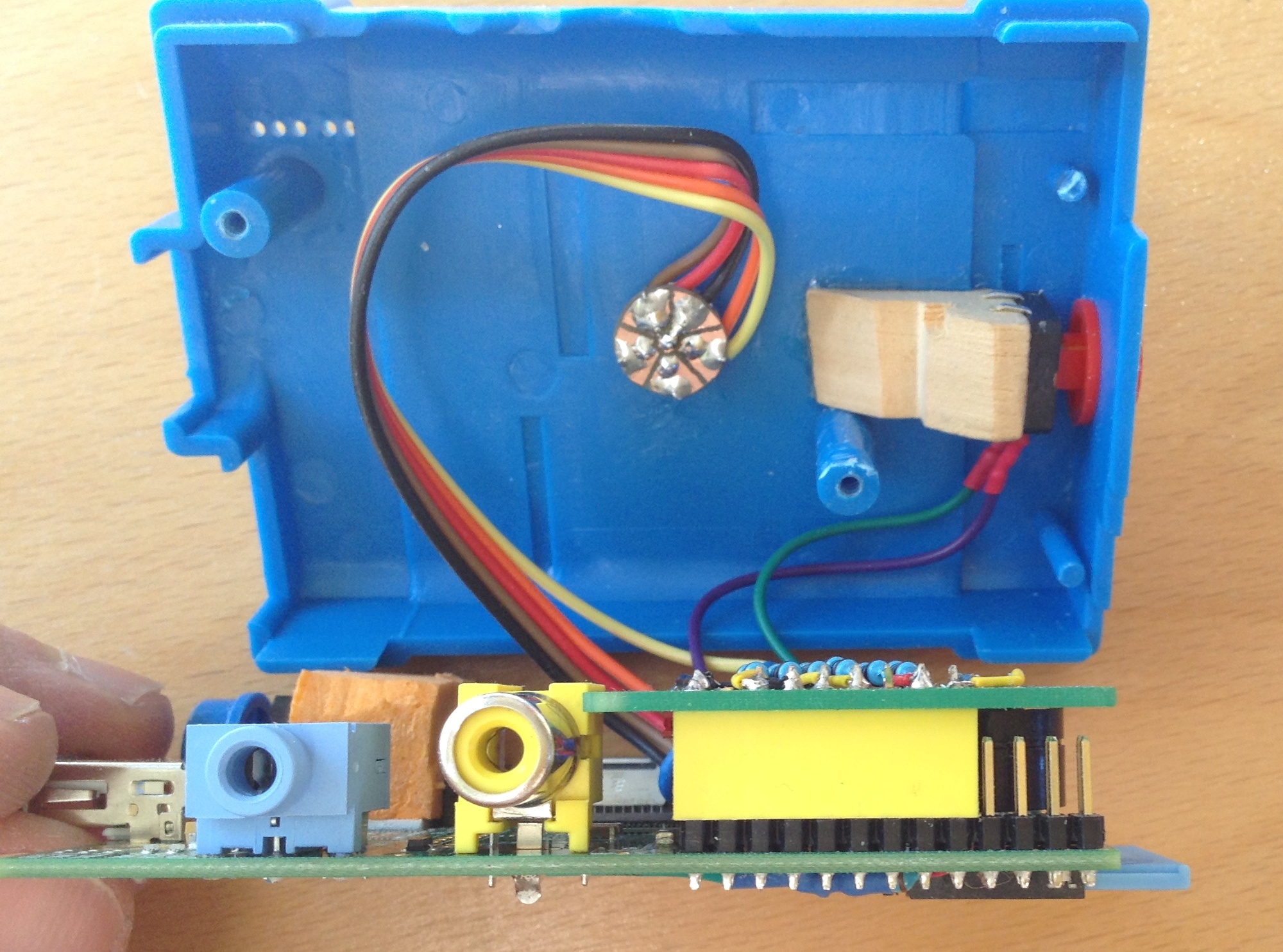
|
 | |