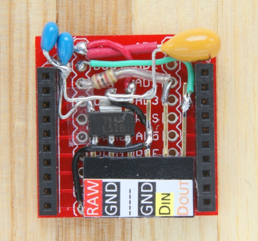
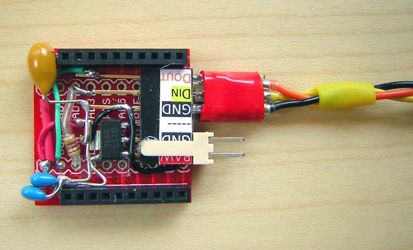
Vario version 3Learning from the experience gained from the previous versions (1 and 2), we have arrived at the present solution, a design which we consider actually meets the implied performance goals of this project: i.e. sensitive indication of lift, proportional signal values, sufficient radio range and negligible mass. The major components: 1) The pressure sensor is once again the reliable Bosch BMP085. 2) For choice of µC board we are back with the Pro Mini 3.3v/8MHz. Simply because it is the smallest and lightest of all the commercially available Arduino variants. 3) The Tx/Rx system comprise a pair of the powerful XBee-PRO 900 MHz modules. This system has a very convenient basic interface in default mode. Most significantly, it also has a nominal (claimed) transmission range of several kilometers! 4) A synthesized speech chip was added to the receiver circuit in order to provide experimental altitude feedback. The hardwareThe physical dimensions of the actual variometer package are similar to the first version, while the Xbee Tx module with its plain wire antenna is kept separate on a satellite adaptor board. 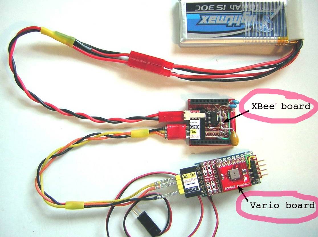 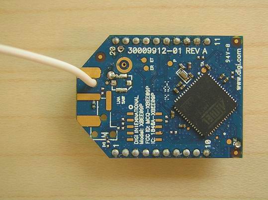 The pressure sensor breakout board sits piggyback on the neat little mini shield (a SparkFun design), which in turn is soldered to the Pro Mini board to form a very compact unit. 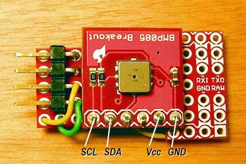 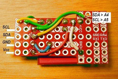 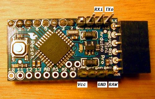 Headers were added to unused I2C and digital pins, for possible future use with additional sensors, etc. 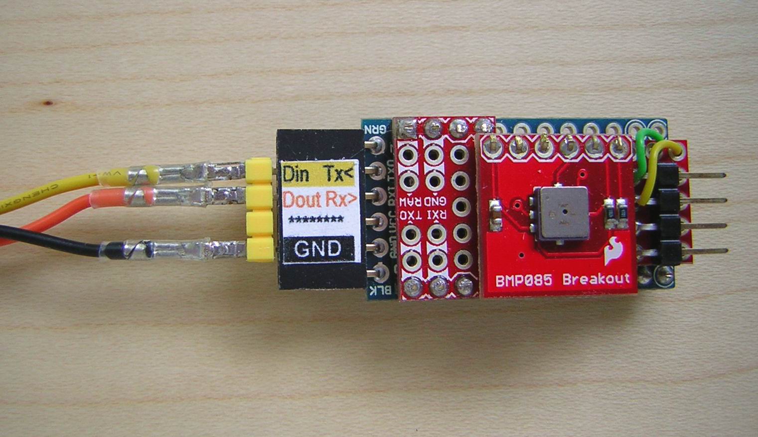 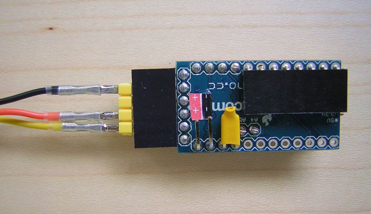 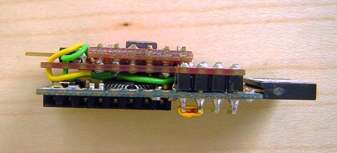 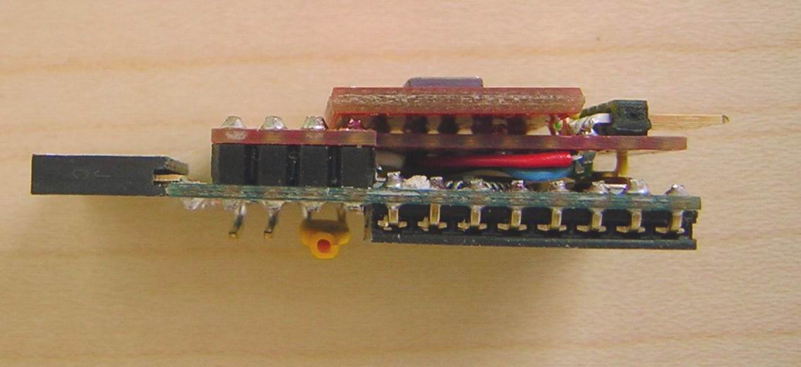 (A variant of this variometer, with an even smaller barometer breakout board arrangement, was built for the BirdBrain project.) The XBee-PRO 900 module is rather powerful and consequently draws about 60-85 mA when transmitting (depending on the frequency of the sketch loop). This indicates that we need a separate power supply, in order not to risk exhausting the Pro Mini's limited onboard regulator. For initial flight testing we used two LiPo 1S 350 mAh batteries in series, producing a nominal 7.4 volts and 350 mAh. This was then regulated down to the required 3.3 volts on the custom XBee adapter board itself *.
  The original schematic for the entire BMP085/Pro Mini/Xbee Tx assembly looked like this: 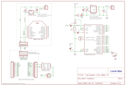 The new version instead uses on a common battery supply for both transmitter and µC, regulated to 3.3 volts by a MIC5219: 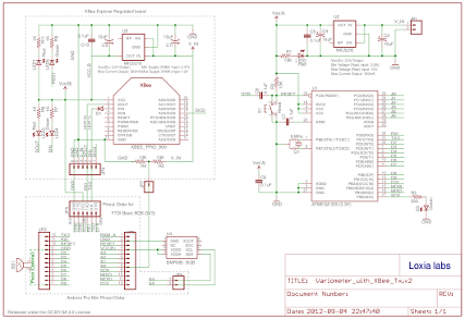 All the components that make up the receiver circuit, including the SpeakJet and its LM386 audio amplifier chip, were squeezed onto a standard sized prototyping shield on top of an Arduino UNO board, and finally housed in a small plastic box similar to the one used for the previous version. As can be seen from the pictures, space for all the through-hole parts is limited, so the XBee module's "daughter board" with its own 3.3V regulator had to be attached off-side. 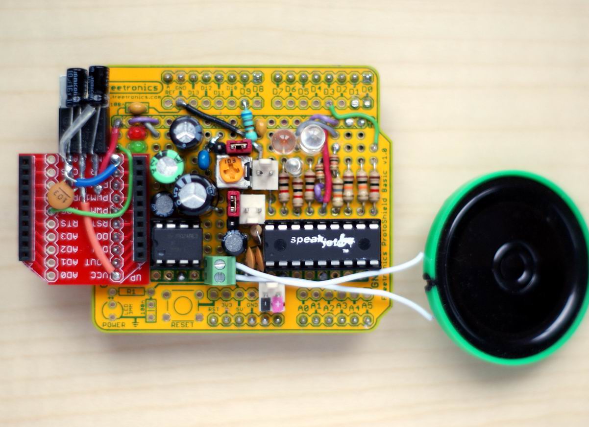 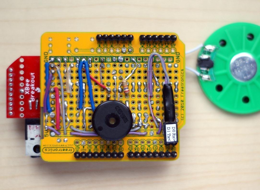 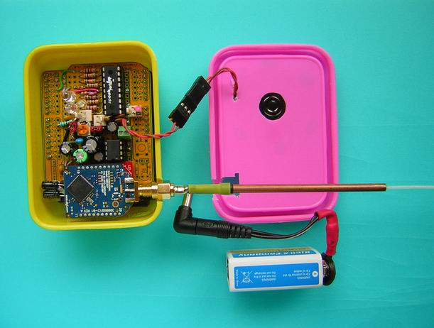  The XBee module chosen for the Rx end has an RP-SMA antenna connector. A simple dipole "stiff duck" antenna tuned to 900 MHz was fabricated from a piece of RG174 coax cable and 4 mm copper tubing. The coax shield braid is simply folded back (inside-out) over the lower part and the snug fitting tube then pushed down to keep everything in place.  This is the schematic for the XBee/Piezo/Speakjet Rx shield:  The softwareSpecific changes to the code for this version are mostly limited to parts that apply to the broadcasting routines, since with XBee technology we use regular UART serial communication instead of the VirtualWire commands. Browsing the Tx-side sketch, it is worth noting that the sensor's pressure data stream is interrogated in the loop to also determine altitude above ground (in 5 m increments), besides the usual vertical speed calculations. A consequence of the fact that we now strive to keep track of the actual altitude, is the need for more accurate (i.e. temperature compensated) real-time pressure data. To this end the earlier simplified sampling routine used with version 2 is replaced by the more elaborate and fully temperature compensated routine outlined in the Bosch API. In the Rx-side sketch a start-up "jingle" indicates the major version number by the number of beeps ("3" in this case). Furthermore, the altitude data is monitored several times a minute for significant changes to the flight level, and if no signal is received for approximately five seconds a short warning beep is sounded. Additional blocks of code have been introduced to support the specific SpeakJet functions which enable the synthetic voice speaker to announce the the model's altitude (presently up to 400 m AGL). Arduino IDE version 0023 was used when developing these sketches. They may or may not work "as is" with version 1.0 and later, but this has not been tested yet. Updates 2013-05-29 Code versions Tx_42/Rx_62 has the following added or improved features:
Flight evaluationThe glider used as a prototype "testbed" this time is a Parkzone Radian, an electric powered 2-meter foam glider equipped with a 2.4GHz Spectrum RC system. The vario and Xbee boards are strapped to a 1 mm plywood deck which bridges the rear part of the cockpit under the plastic canopy. The preliminary hook-up, as pictured below, involved separate batteries feeding the dedicated 3.3V regulators of the µC and the transmitter respectively. This was mainly because we wanted to eliminate the risk of exceeding the Mini Pro's 150 mA rated capacity, and also to electrically isolate the system under test from the flight battery circuit with its heavy-duty ESC and BEC. This scheme worked fine but resulted in a unecessarily heavy system, so we're now using a much lighter setup, employing just one small 350 mAh LiPo cell feeding both Tx and vario via the 500 mA rated regulator of an "Xbee Explorer Regulated" adapter board from SparkFun (substituting the earlier custom adapter board that we managed to kill). This reduced the all-up weight by about 50 grams! A further reduction of about 10 grams should be possible by optionally using the RC Rx battery (i.e. via the BEC in this case) for power.  Since the MIC5219 regulator of the Explorer board has a very low dropout, it will output a steady 3.3V at the required power level (which in lab testing never exceeds circa 100 mA) as long as Vin is at least 3.5 volts. To minimise the risk of letting the battery run below this level, a simple supply voltage check routine (with acoustic output) is performed each time power is turned-on. The performance of this system has met all my expectations. The vario climb signal is received without any noticeable skips from all directions, and from as far away as I dare to fly on a day with good visibility and my best glasses on. The highest documented altitude above ground so far is 702 meters, recorded with an onboard Eagle Tree altimeter. On another occasion I allowed the plane to drift rather too much downwind when it topped-out at 498 m. The approximate inclination of the line-of-sight towards the glider was then perhaps 30 degrees, which means that the actual straight distance between the transmitter and the receiver must have been about 1 km! That's good enough for me! Here are some bonus pictures of the earlier appearance (left hand side) versus the present layout (right hand side): 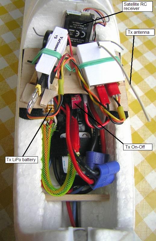 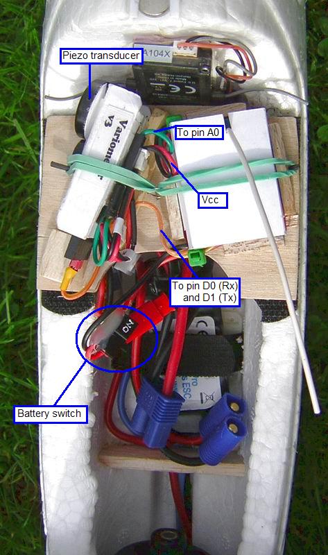 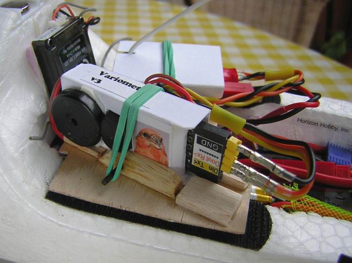 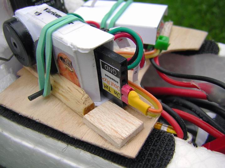 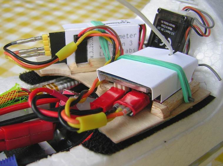 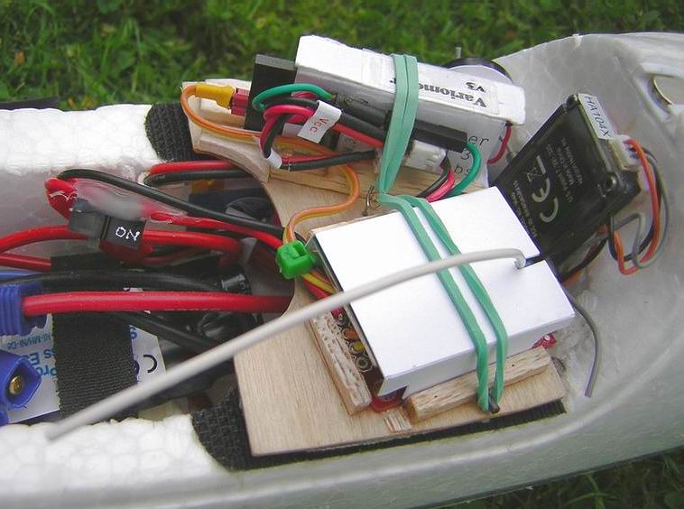 Comments
 You may mail me here: xneb.contact@gmail.com
Resources
Source code files can be found in the Github repository:
https://github.com/moof-moof/variometer-tx-rx
To compile: Move the files xneb3_Tx.pde and xneb3_Rx.pde to their own discrete folders in your Sketchbook folder, and the EWMAcumStiction folder to the arduino/libraries/ folder. The header file Phrases.h should be in the xneb3_Rx folder, as well. 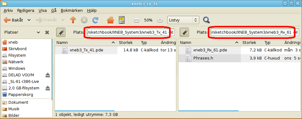 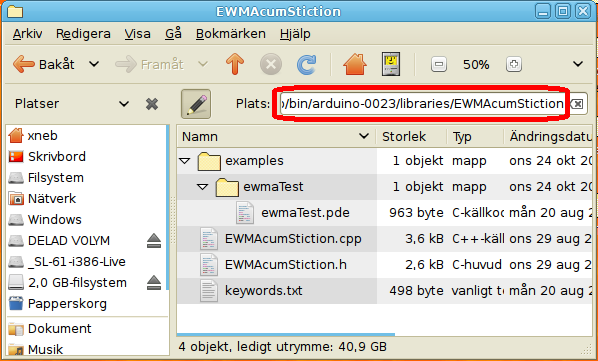  |
 | |