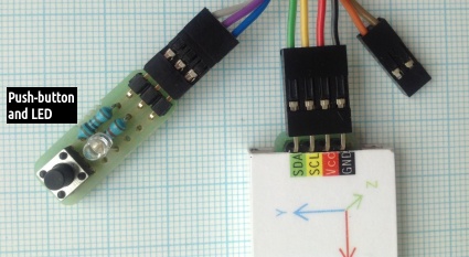
Since the late 1990's there have been a growing number of interesting unmanned aerial vehicle (UAV) projects published, but only a handful of these have aimed at developing autonomous soaring models capable of finding and utilising thermal updrafts (or indeed any sources of lift) in order to stay aloft for an extended flight time. The most well-known and referenced studies in the latter field of research are probably those by J. Wharington; K.G. Egan; Michael J. Allen; and Dan Edwards respectively. Our own humble attempt described here aims simply at presenting an autopilot system that stabilise an inherently semi-stable two-channel model glider when put into a "robotic" mode. It should then either (1) attempt a straight glide in a predetermined direction (typically into the prevailing wind) if there is no usable lift to be found, or (2) circle and drift with the wind whenever an updraft is detected. The guidance and positioning (i.e. navigation) algorithms necessary to effectively centre in the lift in an optimal way remain the object of future development, and hence is beyond the scope of this primary study. Presently a simple programmatic circling behaviour will have to do as "proof of concept". The hardware 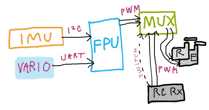 Even a minimal system such as this requires some means of sensing the model's attitude in tri-axis space — what is commonly known as an Inertial Measurement Unit (IMU), or more accurately, a MARG (magnetic, angular rate, gravitational) sensor array. In addition, we want a vertical velocity sensor (variometer), even though it is not actually "fused" in software with the other sensors. The variometer part is the easiest to fulfill, since we can use our own version 3 design! The custom IMU/MARG board we put together for this project consists of three separate sensor chips, each capable of measuring in three axes: An HMC5883L magnetometer, an ADXL345 accelerometer and an ITG-3200 gyroscope. These are mounted on a separate balsa "tray" for protection, so that they can ideally be located some distance away from on-board electronic parts that may emit electro-magnetic noise. It is essential that the sensors are aligned accurately with the main axes of the airframe. To achieve this, the IMU's position must be minutely adjustable so that its normal (neutral) output signals directly represent the empirically determined roll and pitch trim of the airframe. In order to perform the initial calibration of the magnetometer in an environment reasonably void of erroneous magnetic influence, the HMC5883L chip was placed on a wooden stool, standing clear of metal structures, etc. 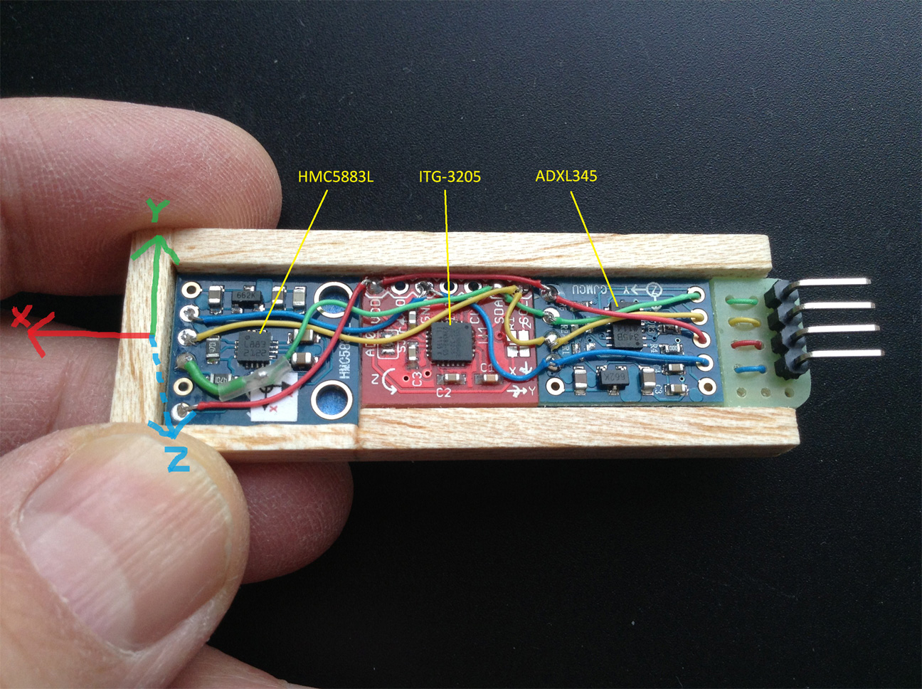 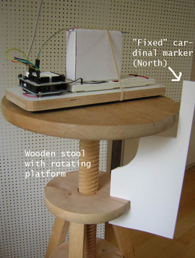 The schematic for the IMU and its connections to an Arduino Pro Mini looks like this: 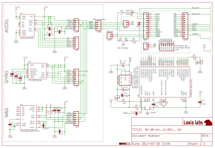 The IMU/MARG sensor array connects to a "flight managment unit" (FMU) — the brain of the autopilot system, as it were. A prototype FMU was assembled in the lab for proving the circuit layout while testing different coding ideas. This testbed employed the Pro Mini's bigger brother the Arduino Pro (8Mhz/3v3 version), running various developing versions of the BirdBrain firmware. In order to be able to remotely transfer servo control from manual R/C mode to the "autopilot" and vice versa, a multiplexer is required. We happened to have the "Failsafe MUX" board from 3DRobotics lying around, so used this (that's the small green board in the picture below). Also, for serving up simulated variometer data to the autopilot's navigation functions, a second Arduino was connected to the UART Rx pin. 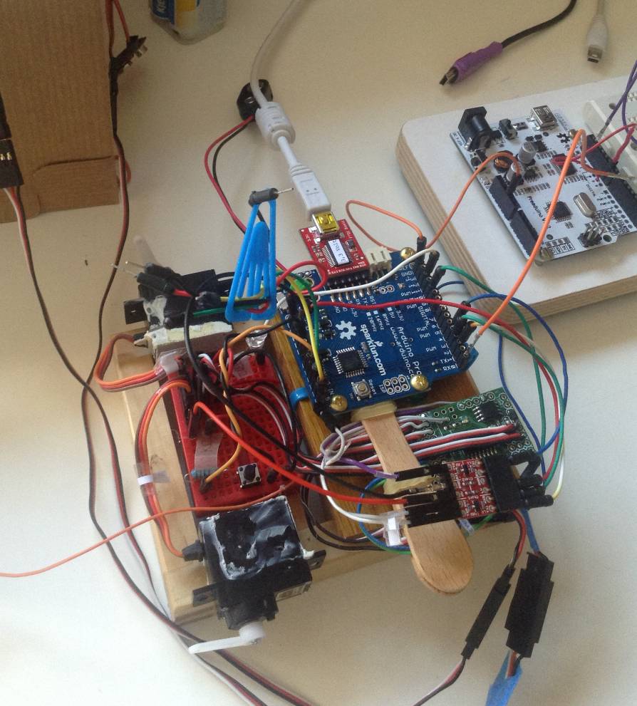 (If one wants to replicate this circuit it is worth noting that the Pro boards have 10K resistors on pins D0/D1, which have to be bypassed for this to work.) When the "bench-testing" results were deemed satisfactory the entire prototype hardware bundle was transferred to a dummy model to better simulate flight movements and to directly observe the reaction of the control surfaces.  The schematic for the multiplexer part of the circuit (below) shows signal voltage translators on some of the connections with the arduino. This is necessary for safe communication between the 3.3v microcontroller and the 5-6v used in the MUX/servo environment: 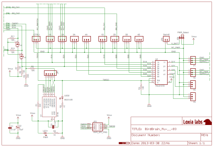 When the feasibility of the general design had been verified, it was time for some serious size and weight reduction! By using the originally intended 3.3v Pro Mini instead of the larger Pro board we are able to cram the entire FMU — that is all electronics except the IMU/MARG and vario — into a conveniently sized tooth-pick case! The classy mouse mat backdrop images below present the front and back aspects. (And the carpet pattern is mid-17th century, Northern India, in case you wonder.) 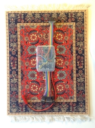 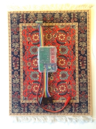 (This close-up may be clicked for a rather larger view) (This close-up may be clicked for a rather larger view) 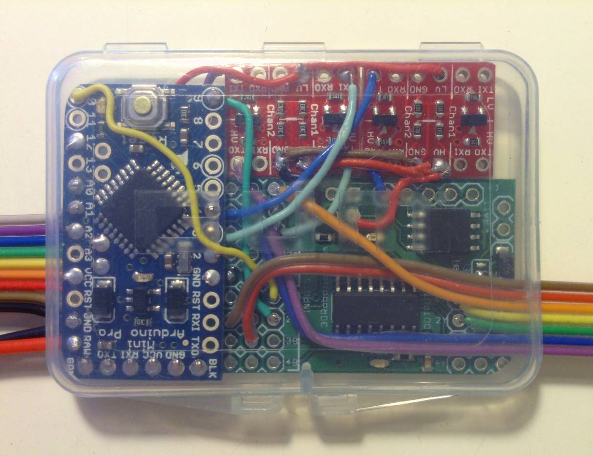 A connector reference image is compulsory at this stage. Trivial hook-up mistakes in the field may have disastrous consequences... 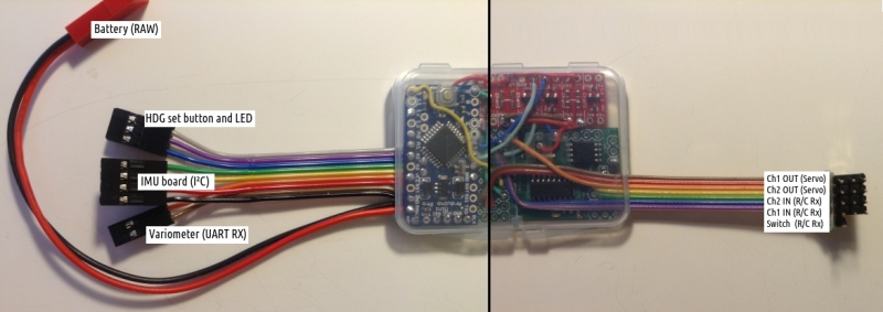 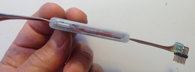 Dimensions of the plastic case is 55*40*7 mm, and the mass is 18.4 g. This weight includes the Arduino Pro Mini, The 3DRobotics Mux-board and two small Sparkfun level-translator breakout-boards, plus the required eighteen wires and their connectors, as shown. Revisiting the question of variometer design optimisation, we took the opportunity to further reduce the size and mass of our earlier vario version 3. A minimalistic (10x10 mm) "Multiwii Barometer BMP085" breakout board, supplied by HobbyKing, is now stuck directly to the back of the Pro Mini board, and replaces the bulkier double-layered solution used earlier. There is now also room for a diminutive audio transducer (7.5x7.5 mm, part SMT-0727-S-R from Projects Unlimited; SG1 in the schematic below). The sound level of this is quite sufficient, and we can use it in software for e.g. battery state signalling and other acoustic feedback. 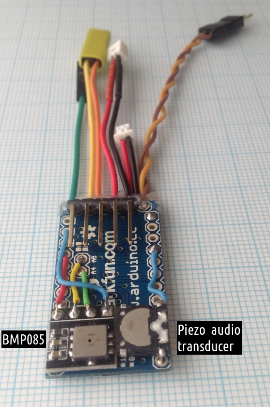  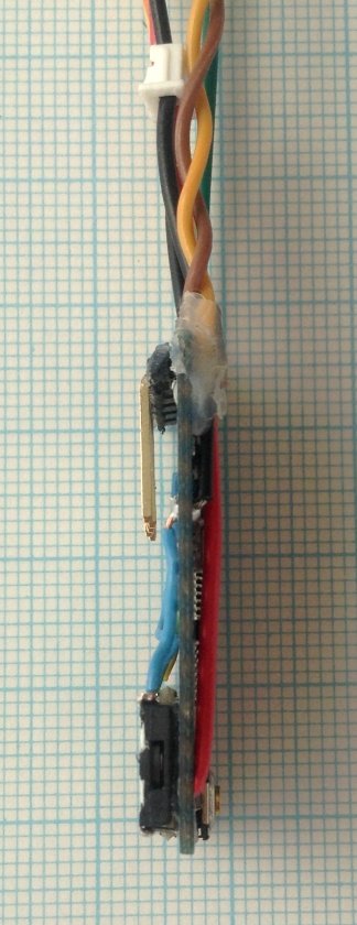 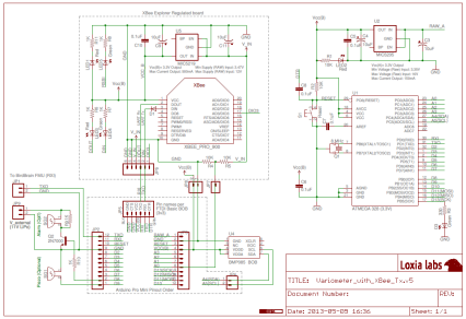 Finally, we can connect all parts to get a more comprehensive picture of the completed system's physical layout: 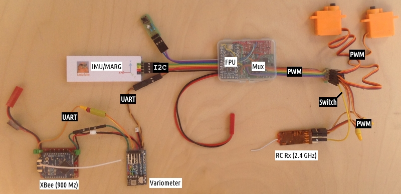 The software The bulk of the code for this project emanates from two separate sources: The Attitude and Heading Reference System (AHRS), which is used for interpreting the IMU data stream through sensor fusion, is a cut-down and simplified version of Peter Bartz's splendid Razor AHRS. The rest of the BirdBrain code is, for the most part, the result of radically reducing DIY Drones' somewhat bloated ArduPilot v2.7.1 code-base to a minimum, keeping only the functions considered strictly necessary for this particular application as a basic autopilot for non-powered gliders. This meant, among other things, that everything having to do with GPS, various obsolete types of sensors, track-following, turnpoint navigation, throttle management, automatic take-offs and landings or egg-dropping (sic), etc, was left out. Some notable "user-interface" features of our application:
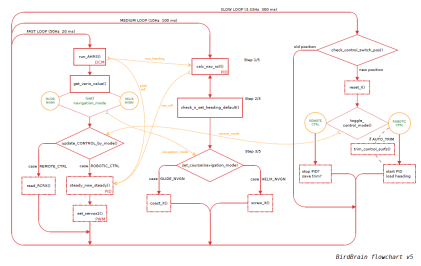
The various system tasks are scheduled to run at different speeds, either 50Hz, 10Hz or 3.33 Hz:
 The ArduPilot projects's stabilisation/navigation routines use the same generic PID implementation found in the Arduino PID library. This is outlined in the first shema below. A potential problem arises whenever the setpoint (i.e. command to the servos) is suddenly changed. Since Error = Setpoint - Input, any change in Setpoint causes an instantaneous change in Error. The derivative of this change may become a really big number and gets fed into the PID equation, resulting in an undesirable spike. This is often called "derivative kick" and is not particularly pretty to behold! 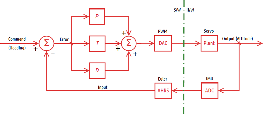 A practical solution to this disturbing phenomenon is to not add (Kd * derivative of Error) to the computation, but instead subtract (Kd * derivative of Input). This is known as "Derivative on Measurement". There is a very clear explanation and walk-through on this and other PID tuning tips here. The second schema below symbolically depicts the implementation we have experimented with (only using the dummy prototype, so far), and it does seem to result in visually smoother transitions. 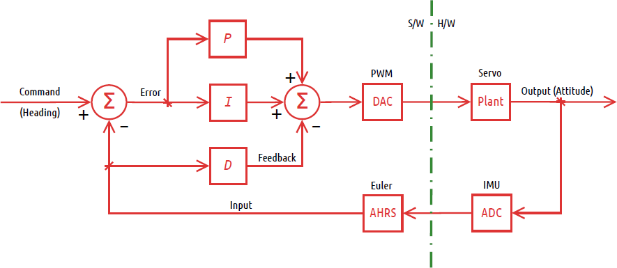 Flight evaluationLorem ipsum: Sed ut perspiciatis unde omnis iste natus error sit voluptatem accusantium doloremque laudantium, totam rem aperiam, eaque ipsa quae ab illo inventore veritatis et quasi architecto beatae vitae PLACEHOLDER sunt explicabo. Nemo enim ipsam voluptatem quia voluptas sit aspernatur aut odit aut fugit, sed quia consequuntur magni dolores eos qui ratione voluptatem sequi nesciunt. Neque porro quisquam est, qui dolorem ipsum quia dolor sit amet, consectetur, adipisci velit, sed quia non numquam eius modi tempora incidunt ut labore et dolore magnam aliquam quaerat voluptatem. Ut enim ad minima veniam, quis nostrum exercitationem ullam corporis suscipit laboriosam, nisi ut aliquid ex ea commodi consequatur? Quis autem vel eum iure reprehenderit qui in ea voluptate velit esse quam nihil molestiae consequatur, vel illum qui dolorem eum fugiat quo voluptas nulla pariatur? At vero eos et accusamus et iusto odio dignissimos ducimus qui blanditiis praesentium voluptatum deleniti atque corrupti quos dolores et quas molestias excepturi sint occaecati cupiditate non provident, similique sunt in culpa qui officia deserunt mollitia animi, id est laborum et dolorum fuga. Et harum quidem rerum facilis est et expedita distinctio. libero tempore, cum soluta nobis est eligendi optio cumque nihil impedit quo minus id quod maxime placeat facere possimus, omnis voluptas assumenda est, omnis dolor repellendus. Temporibus autem quibusdam et aut officiis debitis aut rerum necessitatibus saepe eveniet ut et voluptates repudiandae sint et molestiae non recusandae. Itaque earum rerum hic tenetur a sapiente delectus, ut aut reiciendis voluptatibus maiores alias consequatur aut perferendis doloribus asperiores repellat. Approximate masses (grams)
Comments  Since there is no regular comments feature with Google Sites, you may mail me here instead: xneb.contact@gmail.com |
 | |