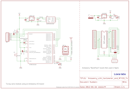
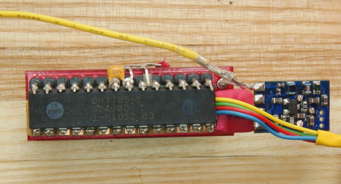
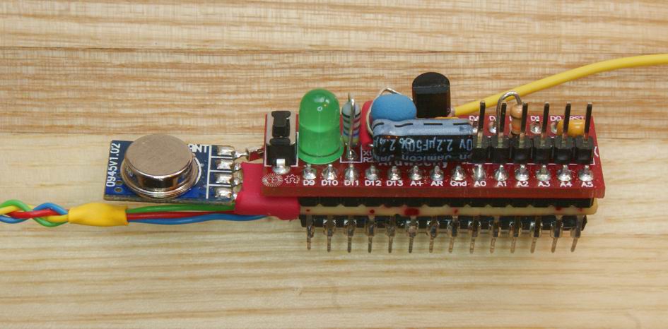
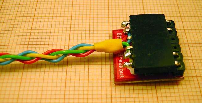
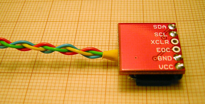
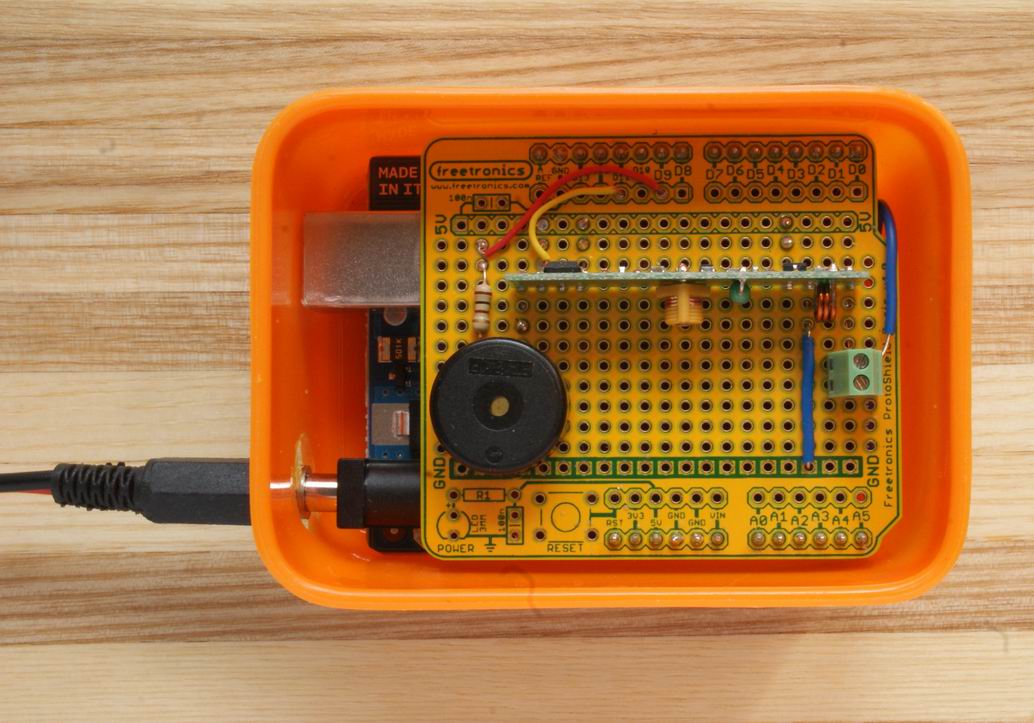
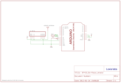
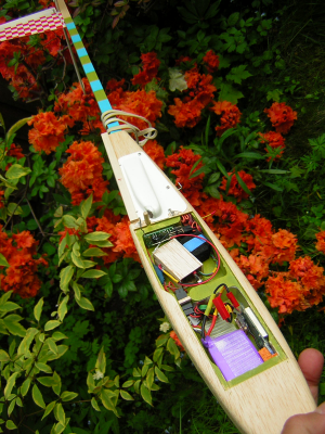
Vario version 2The second iteration in the development cycle of our minimal variometer design differs, hardware-wise, from the first attempt in the following ways: 1) The VTI SCP1000 barometric sensor is replaced by a Bosch BMP085; The decision to use different sensor model was simplified by the fact that the SCP1000, even though adequately sensitive and robust, is no longer manufactured. 2) The clunky "walkie-talkie" hack was abandoned in favour of a regular simplex RF link; That initial transmitter choice was an experiment anyway, and, as it turned out, this was no success. The radio range seemed quite good but the microphone's behaviour was erratic, being much too sensitive to the RF noice generated by onboard electronics. The combination of evident RF frequency emissions from the nearby BEC, and the intermittent chatter and hum (in the aural range) from the servos' action, meant that the beeps could not be discerned reliably most of the time. Well, it was worth a try... 3) The microcontoller board itself is now an "enhanced" Solarbotics Ardweeny instead of the Sparkfun Pro Mini. There was no particular reason for the change of Arduino board type, other than curiosity! The size and shape of the complete package is similar to the previous version. In order to afford some protection, the microcontroller was put in its own balsa box while the sensor is now "broken out" and wrapped up in anti-static foam. 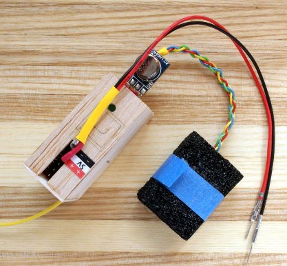 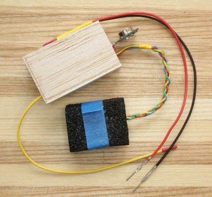 The schematic for the BMP085/Ardweeny/Tx combo looks like this: The tiny no-name 433Mhz transmitter module has a rather limited range, even when operating in line-of-sight conditions -- but much depends on choice of antennas, obviously. When using a basic straight 170 mm wire (and a coiled ditto with the Rx unit) the reliable LOS range probably never exceeds 100 m, even at low bit-rates. This relatively poor performance will have to do for the time being, though. A very slim Tx shield was made. This fits between the legs of the minimalistic Ardweeny board, and on top of the ATmega chip. The separate pressure sensor breakout board is connected to the shield via an "umbilical cord". This makes the assembly less bulky and easier to fit into a space limited fuselage. The Ardweeny is a 5v/16Mhz board (in contrast to the 3.3v/8Mhz of the previously used Pro Mini) and needs an externally regulated power supply. The RF module runs on five volts too, so that's okay. The BMP085, on the other hand, needs 3.3 volts. Nothing is ever simple... To provide the essential 3.3v regulation, an L4931 with the usual capacitors were squeezed on to the already jam-packed PCB of the Ardweeny package. Also shown here is the "BackPack" adapter, used for powering the board during bench testing but unsuitable for service in actual flight. 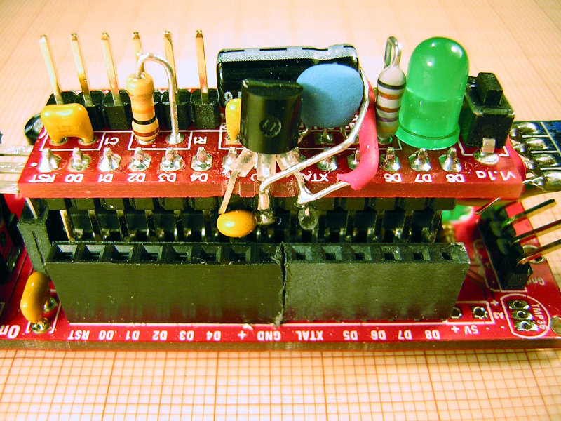 On the receiving end we find the corresponding cheap nameless Rx module sharing a prototyping shield with a piezo transducer. When mounted on an Arduino Uno it all fits into a small plastic box that can be carried in the breast pocket. The unamplified beeps produced from within this container is then easy to hear, without them being so loud as to bother other pilots in the vicinity. And here is the schematic for the receiver shield with its integrated piezo transducer. The softwareThe part of the code that interacts with the sensor and its I2C protocol borrows from various sources, as usual, but mainly from the Bosch API example code. The part that deals with the digital broadcasting uses the VirtualWire library straight off. The variometer specific algorithm, on the other hand, was for the most part re-used from the the previous version, but now accessed via a custom library (named EWMAcumStiction) for convenience. Flight evaluationInitial flight testing was made using an all wood kit glider, the Grosse UHU by Graupner, which has a solid balsa fuselage pod with an easily accesible "cavity", big enough to hold both an 850 mA 3S LiPo flight battery, a BEC, an RC receiver and the vario instrumentation under test. Note attempt at screening off possible RF noise emitting from the BEC in the "front compartment", using material from a beer can. This time the tests were quite succesful; the variometer equipment worked very well as such, quickly indicating any ascent during flight in the expected manner. On the other hand, since the received signal became unreliable and intermittent as soon as the glider reached an altitude greater than approximately 50 meters (and getting worse with more height), it became obvious that the range of this dinky 433Mhz radio system is inadequate for most practical soaring purposes. The obvious answer to this limitation spells Better Radio! Alas, back to the old building board for version 3. Comments
Since there is no regular comments feature with Google Sites, you may mail me here instead: xneb.contact@gmail.com
Resources |

