True Detective truing standTo master the art of lacing and truing spoked bicycle wheels is remarkably satisfying; if not a pure art proper, it is at least a useful craft, and always pleasant therapy. It can also be pursued as an applied science, as shown by Jobst Brandt and numerous others. So it is perhaps not surprising that I have ”always” enjoyed building the wheels for my own bikes, and for the family's ever-growing fleet of twowheelers. All the time I have been meaning to eventually get us a real truing stand, but then too lazy to make one (and too frugal to buy one). Years passed and we just kept on using a makeshift contraption consisting of two old front forks, one of which is widened to approximately fit a rear wheel, and a heavy plank base with a hole drilled into it. Very simple – but unfortunately also fiddly to use if one aspires to great build precision and durability. It can be done, but it ain't fun! Well, at least not as fun as it could be.  Recently my wife and I (not pictured above) decided we needed a couple of new rear wheels for our touring bikes for the coming season. So the rims, hubs and heavy-duty spokes were sourced and ordered – all high-quality stuff just as it should be for serious touring use. However the prospect of building two such potentially critical wheels, while still relying on that embarrassingly floppy old stand, now felt... well, uninspiring. This was clearly an opportunity to justify a ”significantly improved” trueing stand at last! Ideally, this would be a design which was possible to fabricate mainly with parts we already had at our disposal, yet be equipped with accurate measuring means similar to professional tools like those from DT, P&K Lie, et al! 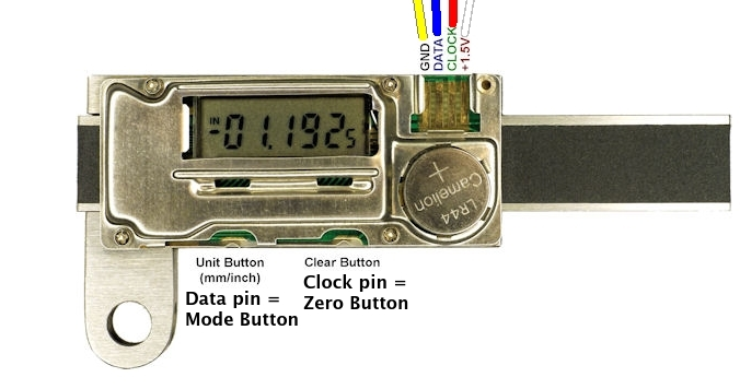 A closer investigation of our stash of aluminium channel cut-offs, composite boards, fine woods and lumber, and various surplus hardware from previous home improvement projects etc, suggested that at least the structural and mechanical aspects could be more or less solved using those basic hacking resources. All that was lacking then was the specialised sensor components. That's when I recalled a review I had seen a while ago, mentioning a surprisingly cheap but sophisticated electronic measuring device – a linear indicator with integrated digital display and supplied with a dedicated data-cable, allowing it to be adapted for remote digital read-out (DRO) and also interfacing with PC applications. Hooray, almost there now! The buildInherent in any reasonably random assembly of hacking materials are all sorts of technical and physical limitations, but also an unknown number of potential opportunities and undiscovered uses. In view of this ”profound insight”, it would be a waste of time to begin a project such as this by making detailed plans and drawings for the expected end product. Instead, invention, inspiration and ultimately solutions tend to appear ”organically” during the actual hands-on building process. Nevertheless, the following properties were deemed critical for an adequate truing stand:
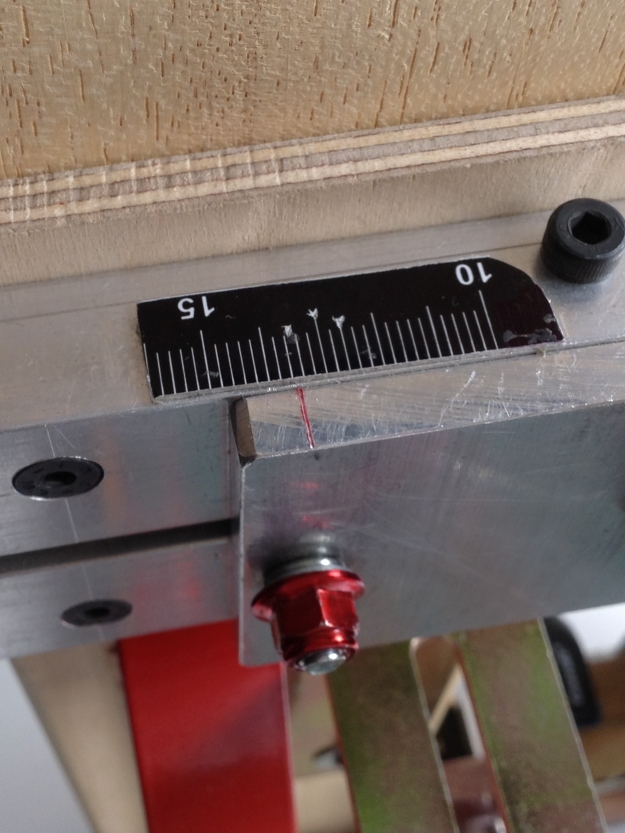
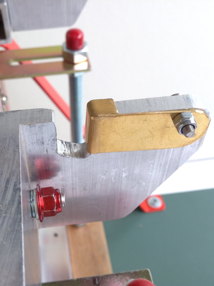
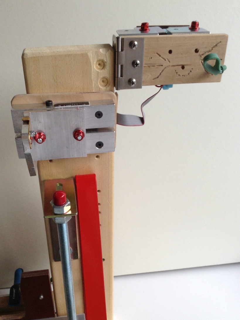
A couple of further decisions were made at an early phase of development: Firstly, that it was essential to be able to accurately detect lateral misalignment, but not so for radial misalignment (the eccentricity, or lack of ”roundness”). As a non-profesional wheel builder I like/need to be slow and deliberate. The radial (up-and-down) dimension of trueness is then rarely a problem to check, in my experience, and may just as well be simultaneously "eye-balled as usual”. Besides, it can be argued that any small bumps in this plane, as a result of slightly varying radii along the rim's perimeter, will probably appear insignificant compared to the typical uneveness of tyres (regardless of brand). Secondly, a facility for exact centering wasn't included in the brief, since it is straightforward to achieve this using a separate dishing tool. The procedure of switching the wheel repeatedly from one tool to another does not improve building speed, but then again, as an enthusiast I don't really mind. Actually I would be disappointed if the fun didn't last long! And here – ta-dah! – is the final result: The DRO True Detective apparatus!   The system hardwareA small ball bearing is fastened to the ”head” of the linear indicator's springloaded plunger/slide/spindle. When the bicycle wheel under scrutiny is rotated by hand, this feeler wheel rolls along the wall of the rim, continually scanning the rim's runout by moving the spindle laterally as it passes any deviations from the ideal straight line. The DRO indicator gauge [sensor #1] spits out the measurement data in 48-bit packets to the microcontroller at a rate of either three packets per second in slow mode, or 20 per second in fast mode. The resolution of the gauge device is nominally 23 bits, which of course is overkill. By reading only the most significant 12 bits we still get a decimal resolution of 0.01mm for its entire range of almost 32mm (0 – 3176). The precision (defined as degree of consistency and repeatabilty, barring obvious glitches) for the device itself seems equally good in fact. This means, incidently, that absolute ”trueness” in the sense of identical readings all round the rim circumference would be practically impossible to achieve. You just can't build a wheel that perfect! 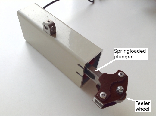  However, there are many potential sources of noise and signal dilution that reduce a sensor's theoretical high level of precision, the most important in our case being the relative flexibility of the wooden fork legs used in this prototype. (Indeed, I still consider this a protype, albeit one I will probably be content with; an improved, non-prototype version would at least have to incorporate a steel fork structure.) It is presently quite possible to make the rim rock sideways a minute amount by (inadvertently) applying a lateral force component when moving the wheel by hand. However, rotating the wheel from near the hub instead of the rim, more or less eliminates this sway. The resulting type of disturbance would technically count as both a random and a systematic error, I guess, thereby influencing both accuracy and precision. Actually accuracy, as such, is not really necessary in this context (since we are not measuring absolute but relative quantities) while reasonable precision is indeed important. Because of this less-than-optimal fork rigidity, I found that a degree of precision measured in tenths of millimeters instead of hundreths is a more realistic assessment. This is still pretty good, I think. The microcontroller, preconfigured for the correct number of spokes, also keeps track of which rim sector each measurement was made in – that is, between which pair of adjacent spokes. This is achieved with the help of a phototransistor [sensor #2] which senses when a laser beam, focused to a pinpoint in the spoke plane, is blocked by each passing spoke (or nipple, actually). 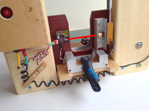 If the wheel is stopped and then turned in the opposite direction, the µC will take note of that too and start counting ”backwards” in order to keep track of the present location. This, in turn, is achieved by using an ”optical flow” sensor [sensor #3]. This is a small 30x30 pixel camera (for an optical mouse) pointed at the hub flange, where it detects the direction of rotation.  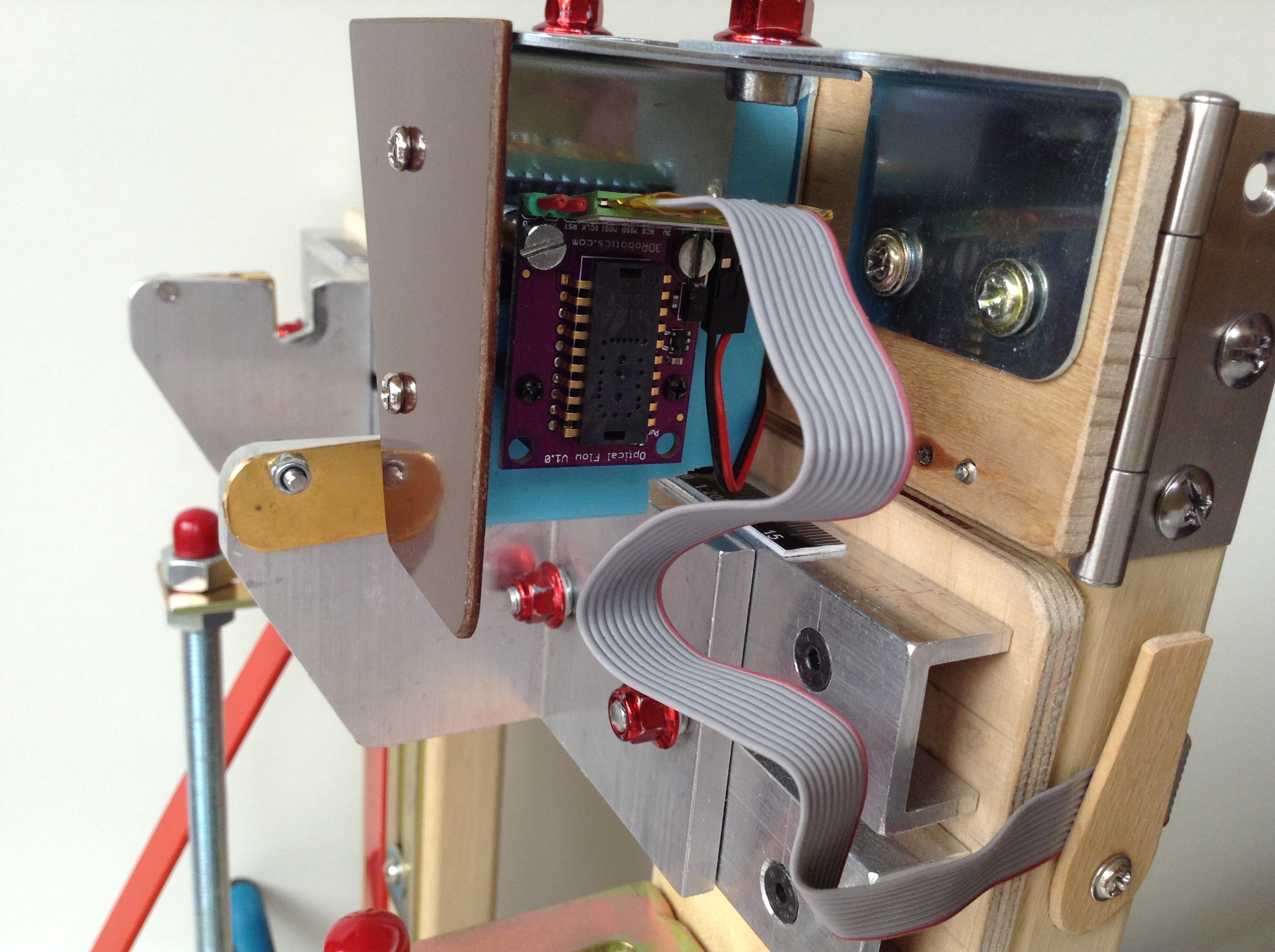 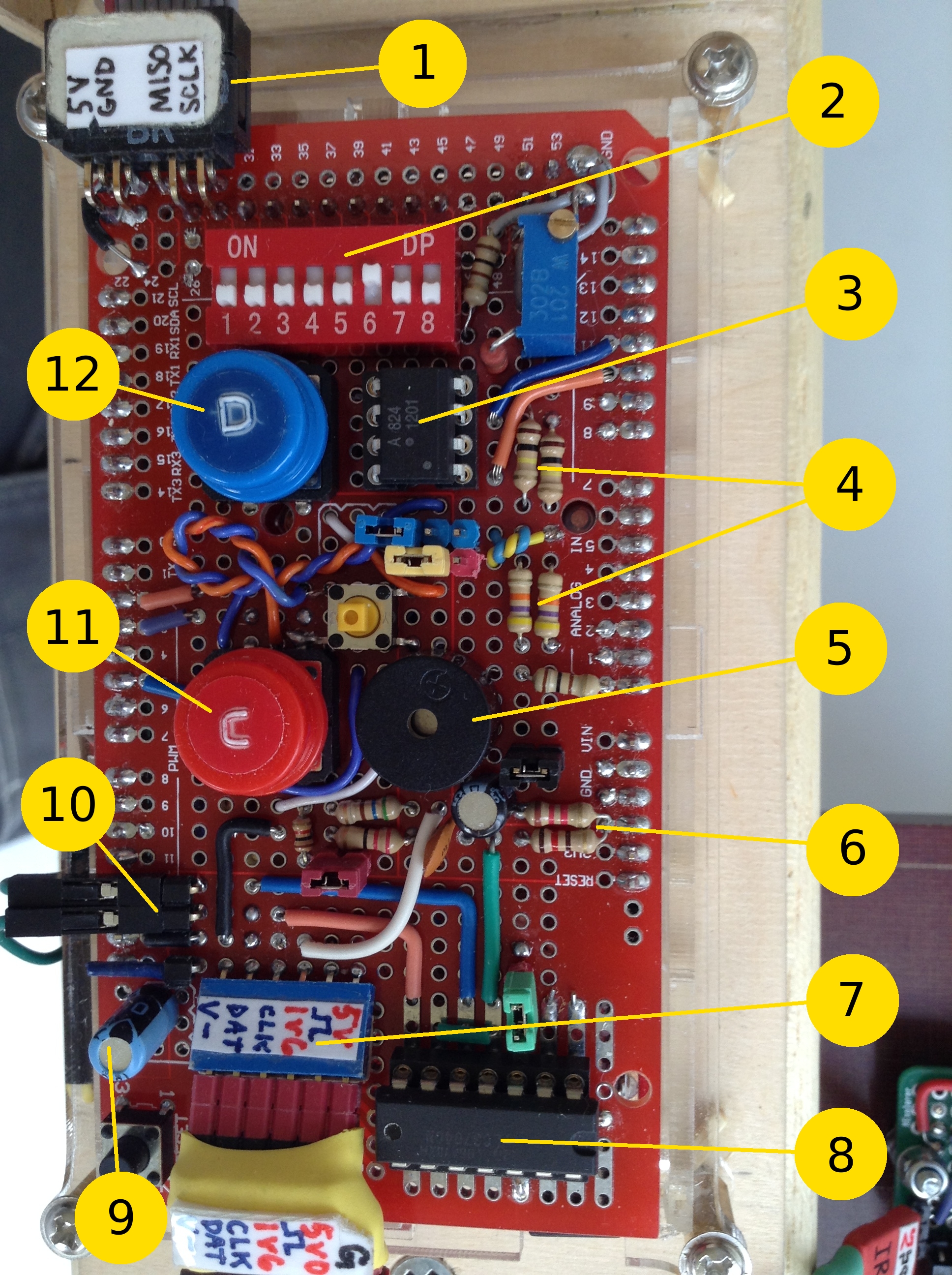
Prominent parts on the Arduino Mega's components "shield":1) Mousecam (sensor #3) input pins 2) DIP switch for selection of the number-of-spokes 3) Optocoupler for automatic zeroing via CLCK-line (see Operation below) 4) Voltage dividing resistors (not used) 5) Piezo beeper 6) Voltage dividing resistors for driving sensor #1 7) Sensor #1 and #2 input pins 8) Operation amplifier 9) Capacitor for blocking automatic reset with serial (not used, notes below) 10) Tick button pins 11) Zero button for manually raising CLCK-line 12) Mode button for manually raising DATA-line The schematicThe electric schematic may seem a little crowded, as it tracks the connections between all the parts of the system (including some experimental components not actually used in the final version) for completeness. 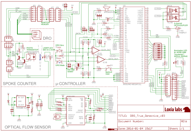 The system softwareThe µC which manages to process all the inputs from the three sensors (after some level-shifting) is an Arduino Mega 2560. It runs the True_Detective_DRO.ino sketch. This code is rather verbosely commented and should be self-explanatory.The software responsible for displaying the rim-curve ”live” is a Processing sketch (Java-code) titled Inspector_Rotam.pde which is run on a PC and receives the data stream serially from the µC by USB at 57600 baud. It then updates the chart's red line-graph, which connects the datapoints, with the measurements closest to each detected spoke along the rim. The graphical result is a horisontal red line, more or less undulating, depending on the rim's degree of (mis)alignment at that point. The centre-most spoke/datapoint in the chart represents the ”zero-spoke”, i.e. the spoke that the operator has set as a temporary zero-value reference point (”ticked”), by pushing the tick button. Below is the layout of the graphing chart. It is shown here in simulation mode, self-generating fake serial signals in the form of a slightly randomised sinusoidal curve, for testing purposes. Click on the picture to watch a small three-frames gif-animation:  OperationThe procedure for setting up a new build and start tightening the spokes depends on whether the critical dimensions of the new wheel are the same as previously, or if adjustments has to be made first. The following steps assume an all new setup.
Below : The "T" button and the reset disabling switch. 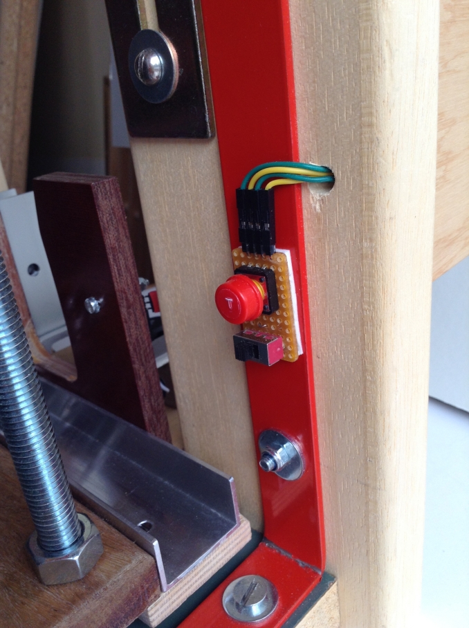 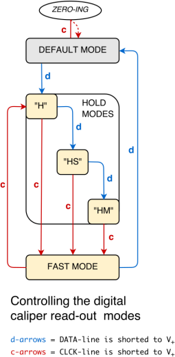 Here's a little action demo with on-screen annotations that explain what is happening. Annoyingly YouTube's annotations technology doesn't always work with mobile devices. For instance, the default YouTube app for iPad completely ignores annotations, whereas watching the same clip in Safari or Chrome (still under iOS) shows them! So you need to watch this in a full web browser for the complete experience! Some hiccups1) There is a default auto-reset circuit built into most types of Arduinos. It is a very convenient feature as long as you are developing, repeatedly flashing new code versions to the microcontroller, but it creates a problem if you need the µC to function independently while you connect and disconnect a serial monitor on you computer. There are at least two simple hacks to disable the automatic resetting. With the first you simply connect a capacitor (about 10 µF) between RESET and GND. I tried that on the MEGA and it worked fine... for a awhile, that is! After several hours the µC suddenly started to misbehave in mysterious ways. I'm not sure what happened, really, but suspect the capacitor just broke down. So we chucked that and went for the radical solution! If you look closely on any standard Arduino PCB (a UNO or a MEGA, at any rate), you will find two solder blobs with a thin trace going between them. If that trace is cut, so is the connection to the RESET pin on the chip, and hence it cannot be reset anymore. Anyway, in order not to forsake the resetting ability completely one can solder on some thin wires to those blobs, and connect them with an ordinary switch. Then just cut the trace with a sharp knife. It looks kind of smudgy in the picture below, because I put on some dabs of silicone to isolate the wire ends. Also, it's a good idea to arrange for some strain relief in the wires in case they get tugged. 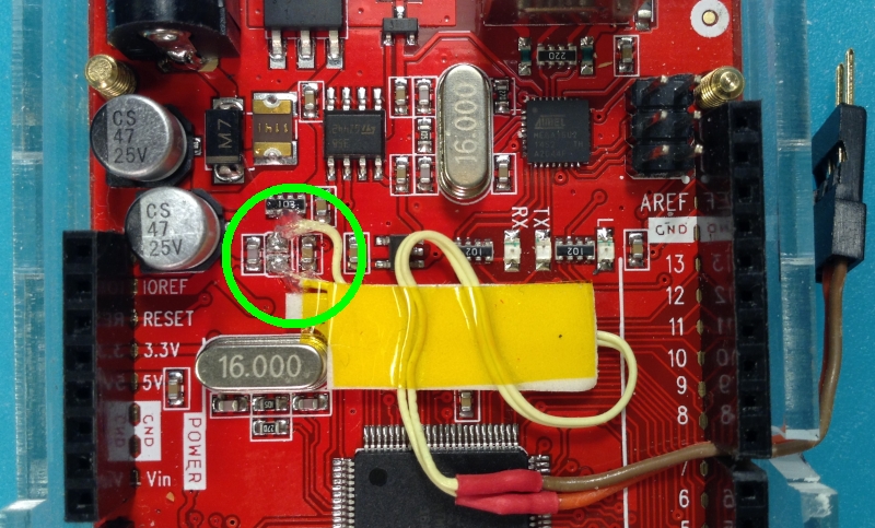 2) Most of the time the values streaming from sensor #1 are very consistent and relatively stable. But occasionally there may be values that are literally "off the charts" and flagrantly false. Other times the faulty values may be closer to the truth but still definitely wrong. These glitches appear to happen more often at specific points in the device's measuring range. Those trouble-spots probably reflect slider positions where the enclosed capacitive linear encoder's discrete "contacts" have been somehow contaminated. All this happens on a microscopic level, mind you. A lot of these glitches can be filtered out in software, but not all. If they start appearing more frequently, a simple remedy is to jog the sensor around laterally until the odd values more or less disappear, and then zero measurements again with the tick-button. Comments  You may mail me here: xneb.contact@gmail.com Source code files can be found in the Github repository: https://github.com/moof-moof/true-detective  |
 | |